Injection Molding Services
We provide reliable injection molding services for producing high-quality plastic parts with fast turnaround, consistent precision, and scalable manufacturing from prototyping to mass production.
Plastic Injection Molding Services
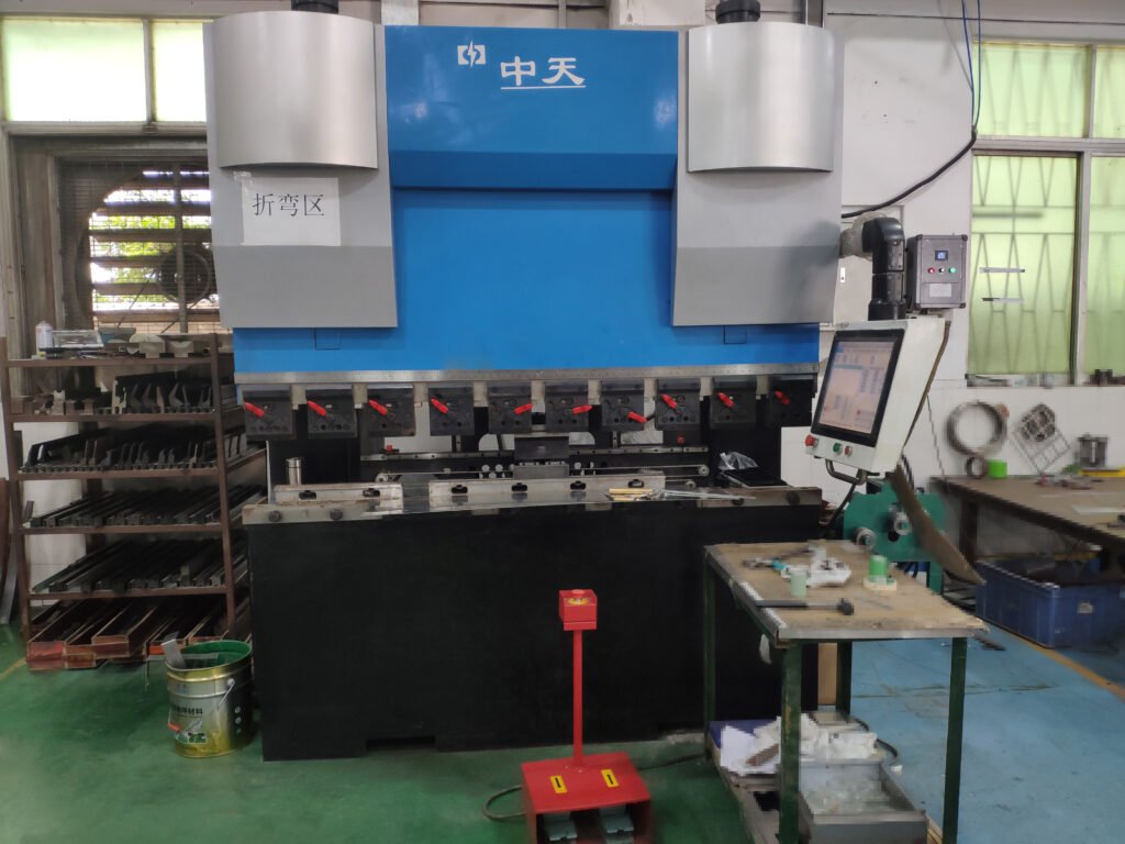
Junvor is a full-service contract manufacturer specializing in custom plastic injection molding. Our advanced manufacturing facility in Shenzhen, China is equipped with a wide range of injection molding machines, enabling us to support projects from prototype development to high-volume production.
We serve a broad spectrum of industries including consumer electronics, industrial equipment, automotive, medical, and energy. Our comprehensive capabilities cover tool design, engineering support, precision molding, assembly, surface finishing, and global logistics.
With a strong commitment to quality, Junvor operates under strict international standards and quality control systems to ensure consistent, reliable results. We deliver precision manufacturing solutions that meet demanding performance requirements while maintaining cost efficiency and scalability.
Services
Get custom plastic prototypes and production parts with flexible and cost-effective solutions from Junvor. We support rapid prototyping and scalable manufacturing to help you move efficiently from concept to production with consistent quality and fast turnaround.
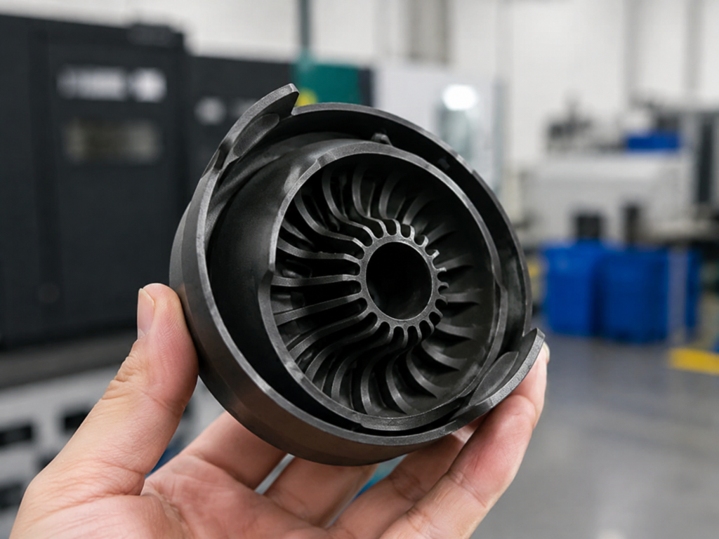
Rapid Prototyping
At Junvor, we provide rapid prototyping services for fast and high-quality plastic parts. With short lead times, flexible materials, and engineering support, we help validate designs quickly and improve product development efficiency.
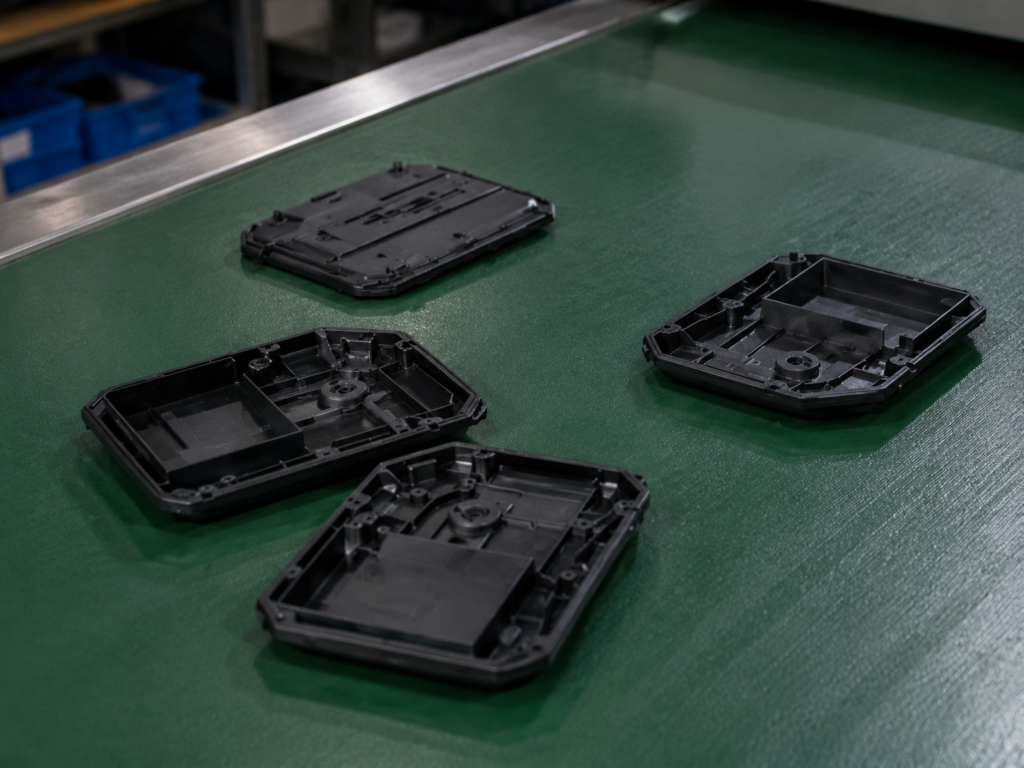
Low Volume Injection Molding
Junvor’s low-volume injection molding services with aluminum tooling offer cost-effective production for hundreds to thousands of parts. Ideal for design validation, pilot runs, and flexible supply chain requirements with stable quality.

Mass Production
Junvor’s high-volume injection molding delivers efficient and scalable manufacturing for precision plastic parts. With advanced equipment and strict quality control, we ensure consistent quality, tight tolerances, and stable mass production output.
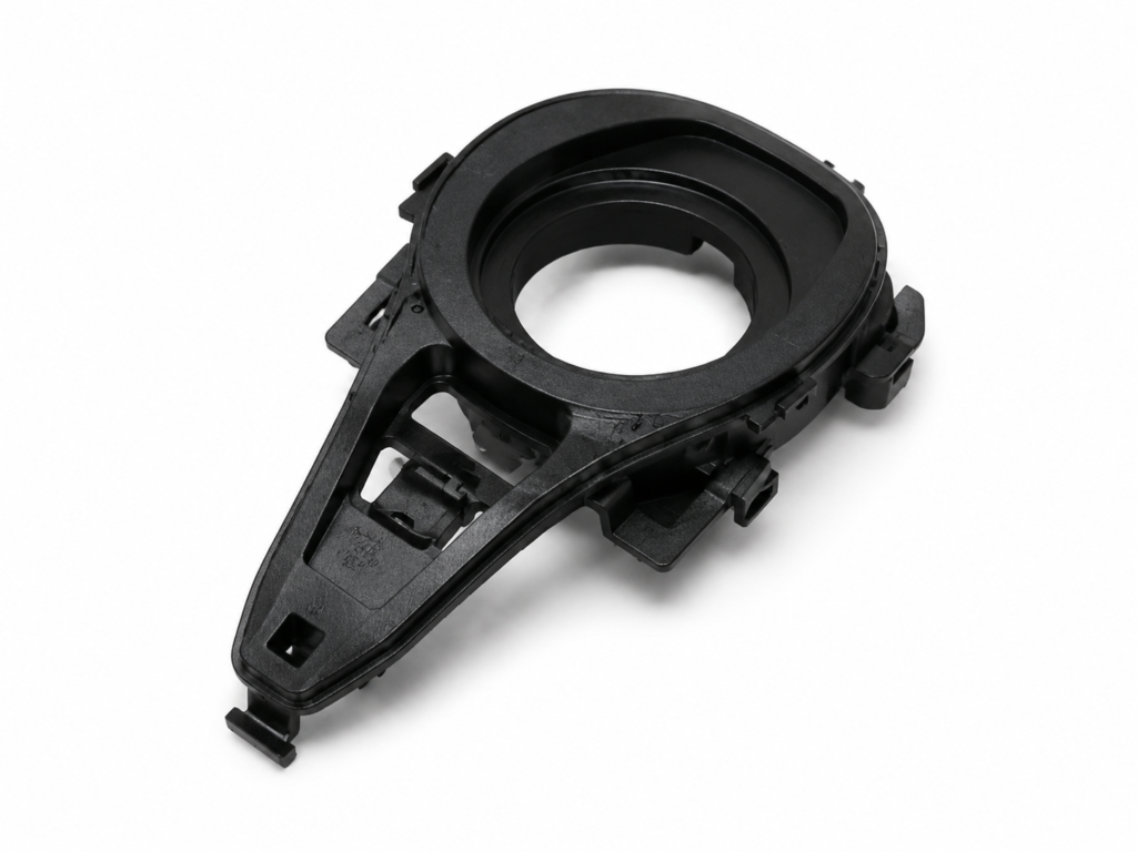
What is injection molding?
Injection molding is a manufacturing process used for mass production of identical plastic parts with high precision and good repeatability. It works by melting thermoplastic pellets and injecting them into a mold, where the material cools and solidifies into the final shape. Additives can be used to adjust color and performance properties.
This process is widely used in industries such as automotive, electronics, and consumer goods due to its low cost per part at high volumes and strong design flexibility. Although tooling requires a higher upfront investment, modern manufacturing workflows have significantly reduced lead times, making production more efficient than ever.
Common injection molding defects
Most injection molding defects are caused by either uneven material flow during filling or inconsistent cooling during solidification. Understanding these issues is essential when designing parts, as proper design practices can effectively prevent common defects and improve overall part quality.
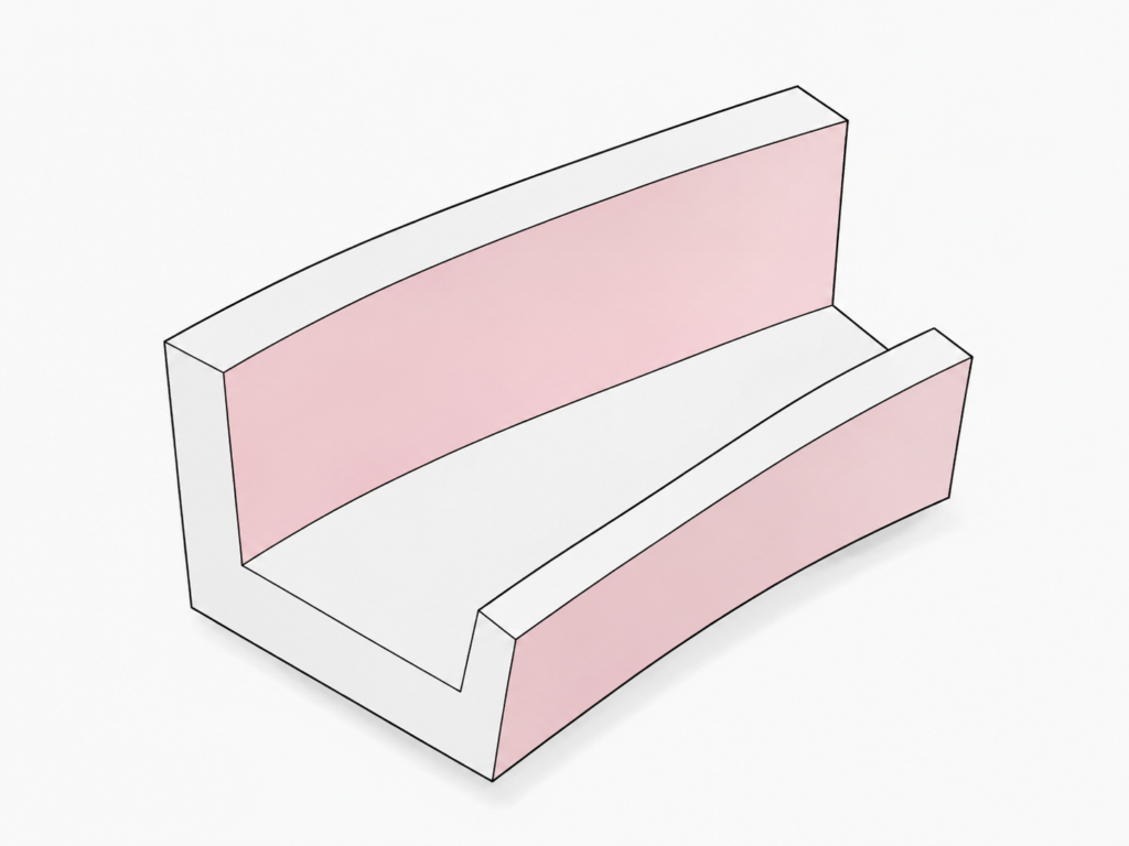
Warping
Warping occurs when different sections of a molded part cool and shrink at uneven rates, creating internal stresses that cause permanent bending or distortion of the component shape.
Parts with non-uniform wall thickness are particularly prone to warping, as uneven cooling leads to stress imbalance across the structure, affecting dimensional accuracy and part performance.
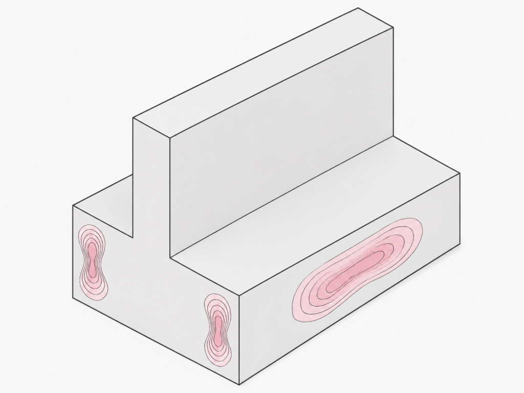
Sink Marks
Sink marks appear when the inner section of a plastic part cools and solidifies more slowly than the outer surface, resulting in small depressions or indentations on otherwise smooth surfaces.
This issue is most common in thick-walled areas or poorly designed ribs, where uneven material shrinkage creates surface inconsistencies that negatively affect both appearance and quality.
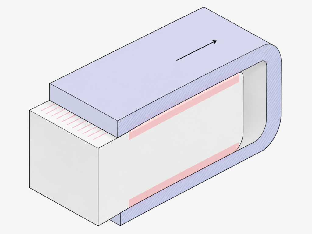
Drag Marks
Drag marks occur during the ejection stage when the molded part sticks slightly to the mold surface and is scraped along the cavity walls as it is released from the tool.
Vertical walls without proper draft angles are especially susceptible, as insufficient release geometry increases friction between the part and mold, leaving visible surface scratches.
Knit Lines
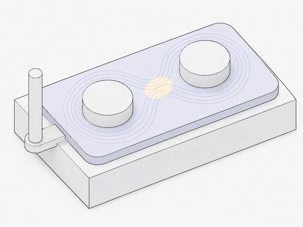
Knit lines form when two or more molten plastic flow fronts meet during injection but fail to fully fuse, leaving visible lines or weak bonding areas on the final part surface.
They commonly occur in parts with holes or sudden geometry changes, where flow separation and recombination reduce both aesthetic quality and structural strength.
Designing Out Undercuts for Cost-Effective Molding
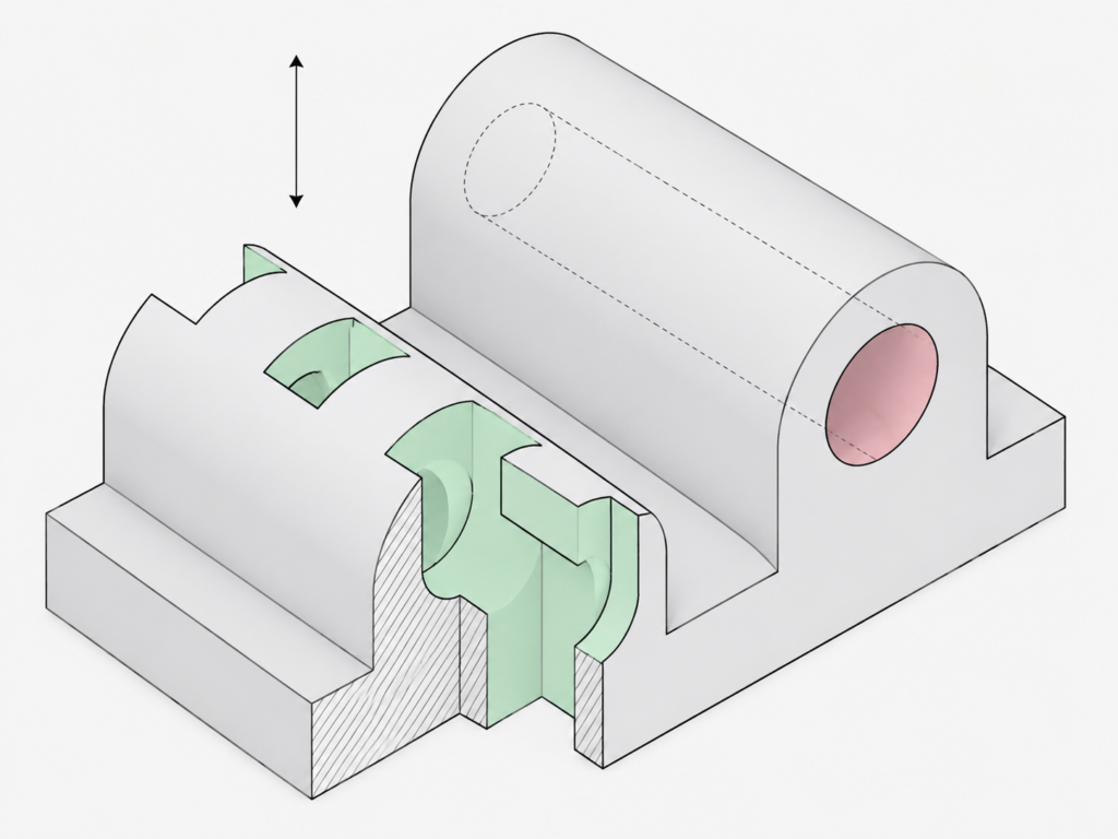
Undercuts in injection-molded parts can significantly increase tooling complexity, cost, and maintenance requirements. In many cases, redesigning the geometry is the most efficient way to eliminate the need for complex mold mechanisms such as sliders or lifters.
For internal features such as snap fits or interference structures, or side features like holes and handles, a shut-off or simplified open design is often a more reliable and cost-effective engineering approach. This helps improve mold durability, reduce production risks, and ensure stable, repeatable manufacturing performance.
What Makes Us Different?
Our competitive advantage is built on four core pillars that guide every aspect of our operations—from production on the shop floor to the way we collaborate with and support our customers.

People
Our team drives success through engineering expertise, collaboration, and shared core values.

Engineering Expertise
We combine deep technical knowledge with practical manufacturing experience to deliver reliable solutions.

Process Control
Strict process control ensures consistent quality, stable production, and on-time delivery.

Quality Assurance
We apply advanced inspection systems to ensure defect-free parts that meet global standards.

Technology & Equipment
We invest in modern injection molding machines, tooling, and support systems for precision production.

Culture & Responsibility
We foster a culture of ownership, teamwork, and continuous improvement across every operation.
Reliable Fastening Points for Stronger Assembly Performance
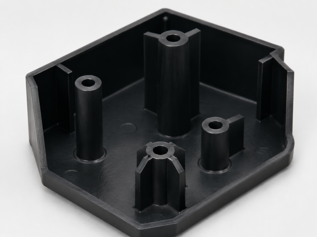
Injection molded parts often require secure and repeatable fastening points, especially in assemblies involving screws, inserts, or mechanical joining. Poorly designed bosses can lead to cracking, loosening, or long-term structural failure.
Our engineered boss design ensures stable load distribution and improved fastening strength by optimizing wall thickness, geometry, and support structure. This helps prevent stress concentration and ensures reliable performance in repeated assembly and high-load applications.
Ready To Get Started?
Contact us to turn your manufacturing concepts into real, production-ready solutions. Our engineering team is ready to review your requirements and provide reliable, quality-focused support from design to final production.
Press-Fit Design in Injection Molding
Interference Fit Control
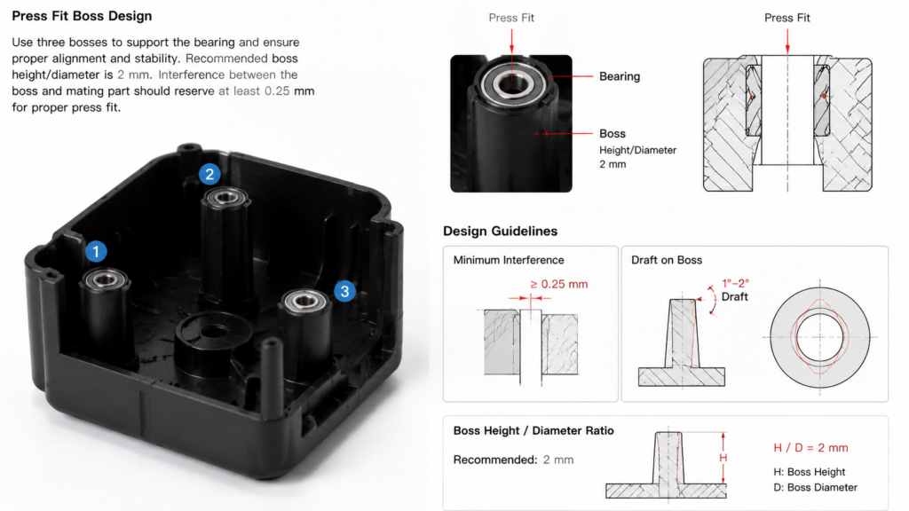
Proper interference is essential in press-fit applications for injection molded parts. A typical recommended interference of ≥0.25 mm ensures secure retention of components such as bearings or metal inserts, preventing loosening during assembly and long-term use.
Boss Geometry Design
Boss structures must be designed with sufficient mechanical support to withstand insertion forces. Recommended practices include optimized wall thickness, R2 mm fillets, and balanced geometry to reduce stress concentration and minimize the risk of cracking during press-fit assembly.
Draft Angle & Stress Management
A proper draft angle is required to reduce insertion resistance and ensure smooth assembly. Combined with controlled wall transitions, it helps minimize surface damage, reduce ejection stress, and prevent long-term failure caused by internal stress accumulation.
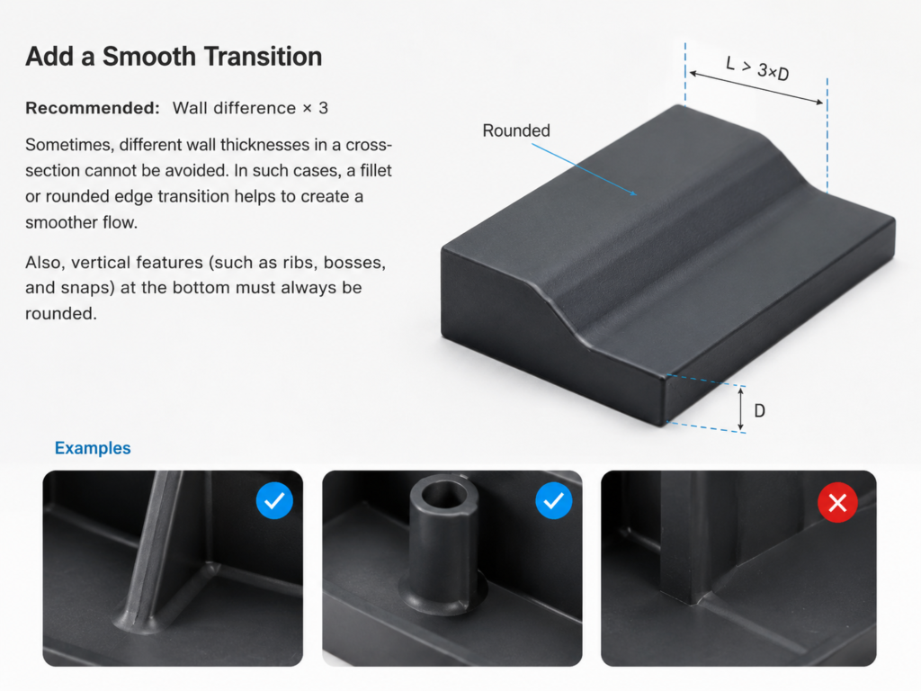
Smooth Transitions for Improved Structural Integrity in Injection Molding
In injection-molded parts, abrupt changes in wall thickness can lead to uneven cooling, internal stress, and potential part deformation. Adding a smooth transition through fillets or rounded edges helps maintain consistent material flow and improves overall structural stability during both molding and cooling stages.
To ensure optimal performance, it is recommended to follow a transition ratio of at least 3× the wall thickness difference. Rounded features should also be applied to vertical elements such as ribs, bosses, and snaps, reducing stress concentration and improving mold release while enhancing part durability and manufacturability.
Materials used for injection molding
Injection molding material selection depends on mechanical performance, temperature, chemical exposure, appearance, shrinkage, moisture sensitivity, regulatory needs, and production volume. Share the intended application and operating environment so resin options and design risks can be reviewed before tooling.
Polypropylene (PP)
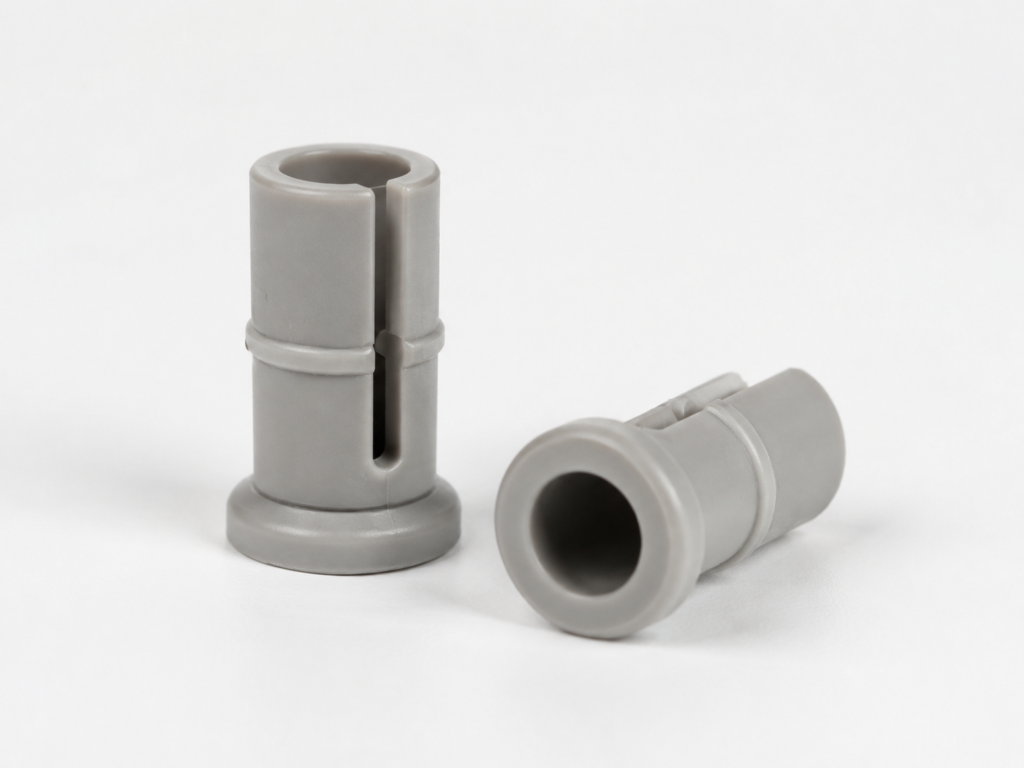
Most widely used injection molding plastic with excellent chemical resistance and food-safe grades.
ABS
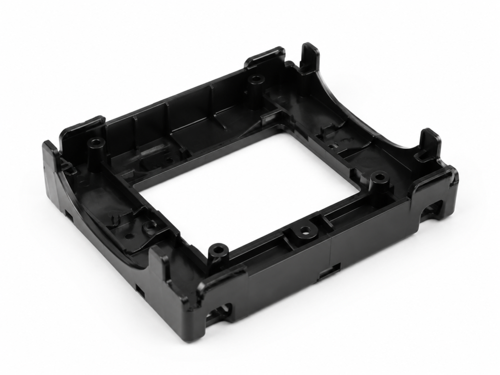
Low-cost thermoplastic with good impact resistance and low density, but limited solvent resistance.
Polyethylene (PE)
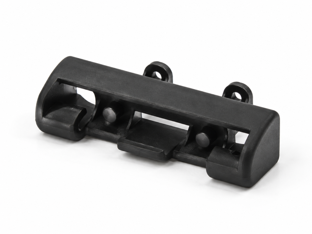
Lightweight material with good impact strength and weather resistance, suitable for outdoor use.
Polystyrene (PS)
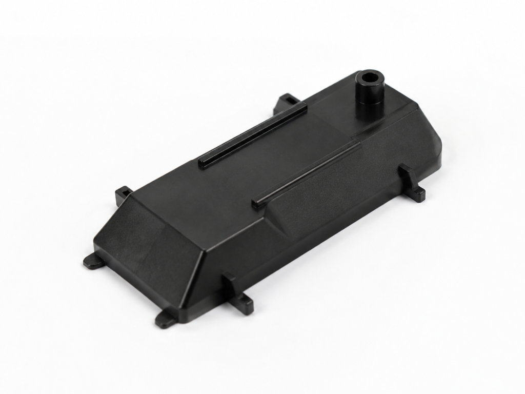
Lowest-cost injection molding plastic, available in food-safe grades but not suitable for structural use.
Polyurethane (PU)
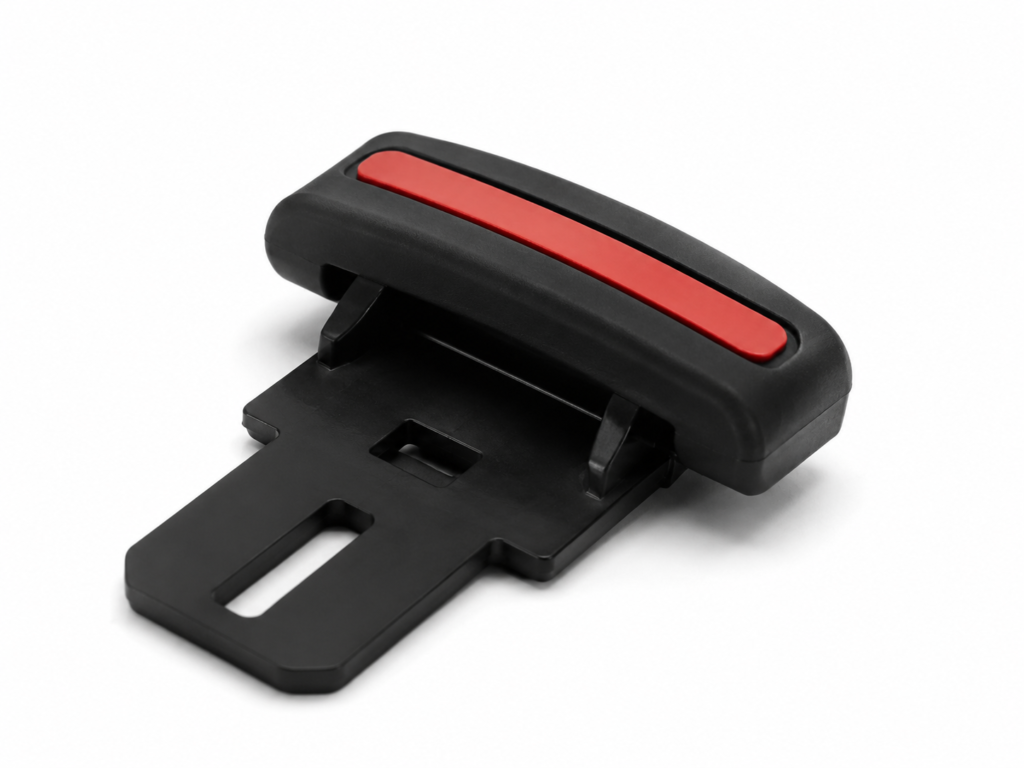
High-impact thermoplastic with good hardness and mechanical performance, ideal for thick-wall parts.
Nylon (PA 6)
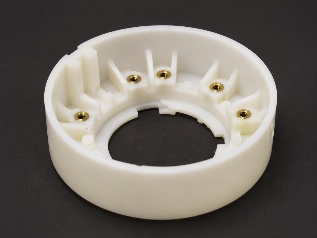
Engineering plastic with excellent strength, abrasion resistance, and chemical resistance, but moisture-sensitive.
Polycarbonate (PC)
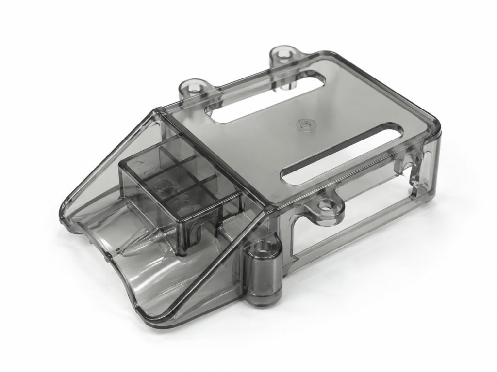
High-impact and heat-resistant plastic with excellent toughness, transparency, and weather durability.
PC/ABS
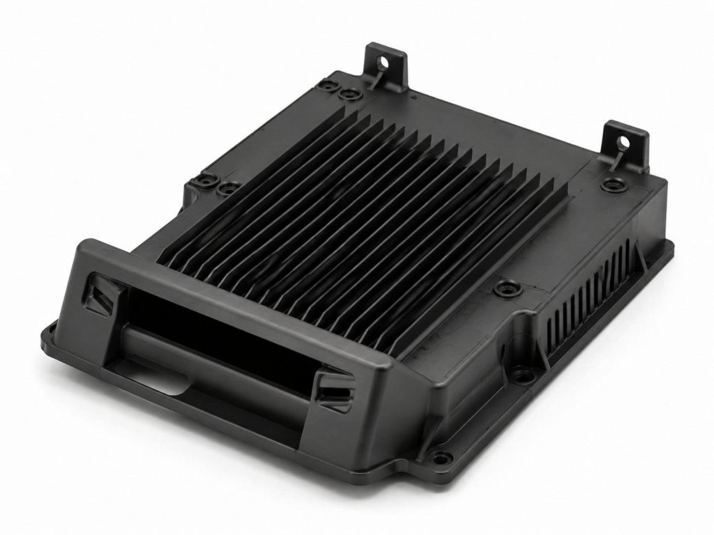
Engineered blend offering high impact strength, thermal stability, and stiffness, but limited chemical resistance.
| Material | Characteristics | Price Level | Technical Information | Applications | Datasheet |
|---|---|---|---|---|---|
ABS Acrylonitrile Butadiene Styrene |
+ Good impact resistance + Excellent dimensional stability + Easy to mold complex structures – UV & heat sensitivity |
$ $ | Shrinkage: 0.4%–0.8% Tolerance: ±0.005–0.010 in |
Automotive parts, electronics housings, appliances | Download |
PP Polypropylene |
+ Lightweight & low cost + Chemical resistance – Lower mechanical strength – Warping risk |
$ | Shrinkage: 1.0%–2.5% Tolerance: ±0.005–0.010 in |
Packaging, containers, medical parts | Download |
PA6 Polyamide 6 |
+ High strength & toughness + Good chemical resistance – Moisture absorption – Dimensional changes |
$ $ $ | Shrinkage: 1.5%–3.0% Tolerance: ±0.005–0.010 in |
Gears, bearings, industrial parts | Download |
PMMA Acrylic |
+ Excellent optical clarity + Weather resistant – Scratch sensitive – Brittle under stress |
$ $ $ | Shrinkage: 0.2%–1.5% Tolerance: ±0.005–0.010 in |
Lighting, lenses, display panels | Download |
PC Polycarbonate |
+ High impact resistance + Heat resistance – Higher cost – Processing shrinkage |
$ $ $ $ | Shrinkage: 0.5%–0.8% Tolerance: ±0.005–0.010 in |
Electronics, automotive, safety equipment | Download |
POM Acetal |
+ High stiffness & strength + Low friction – UV sensitivity – Moderate cost |
$ $ $ | Shrinkage: 1.5%–2.5% Tolerance: ±0.005–0.010 in |
Gears, precision parts, bearings | Download |
PEEK High-performance polymer |
+ Ultra-high strength + Heat & chemical resistance – Very high cost – Difficult processing |
$ $ $ $ $ | Shrinkage: 1.0%–3.0% Tolerance: ±0.002–0.005 in |
Aerospace, medical, high-end engineering | Download |
Cost Reduction Techniques in Injection Molding
Tip 1: Use Straight-Pull Molds Whenever Possible
Straight-pull tooling is generally simpler than molds that require side actions, lifters, collapsible cores, or other moving mechanisms. Reviewing undercuts, shutoffs, draft, parting lines, and ejection early can reduce tooling complexity and make long-term maintenance easier.
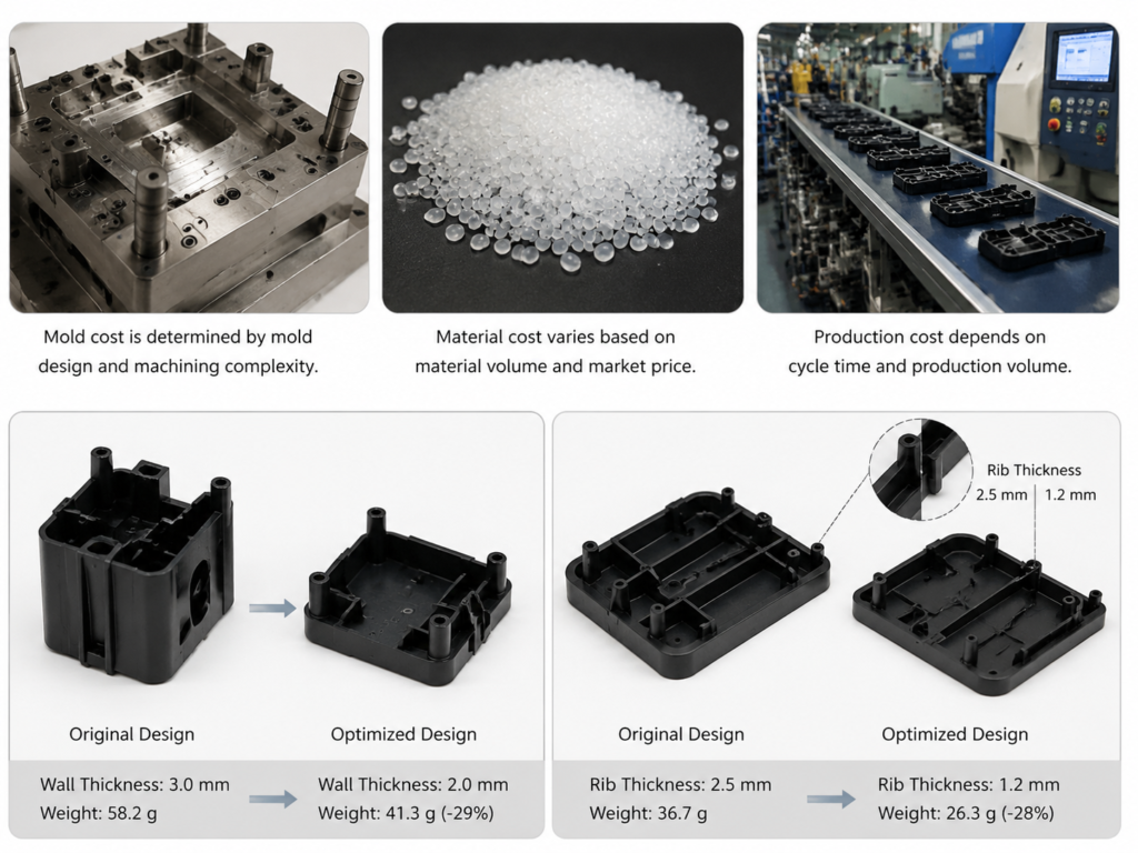
Tips 2–8: Injection Molding Cost Optimization
Undercuts, excessive part complexity, and non-optimized geometry significantly increase mold cost, tooling complexity, and production time. Most undercuts can be eliminated through smart design adjustments such as simplifying geometry and optimizing parting lines, which helps reduce the need for side actions and improves manufacturability. At the same time, reducing part size lowers material usage, shortens cycle time, and decreases overall production cost.
Further cost savings can be achieved by combining multiple parts into a single mold, which improves production efficiency and reduces tooling investment. Simplifying non-functional details and using standard surface finishes also helps minimize machining time and manual processing cost without affecting part performance or functionality.
Additional optimization strategies include reducing wall thickness to improve cooling efficiency and shorten cycle time. For low-volume production, secondary operations such as drilling or post-machining can replace complex mold features, offering a more flexible and cost-effective manufacturing approach.
Start small and prototype fast
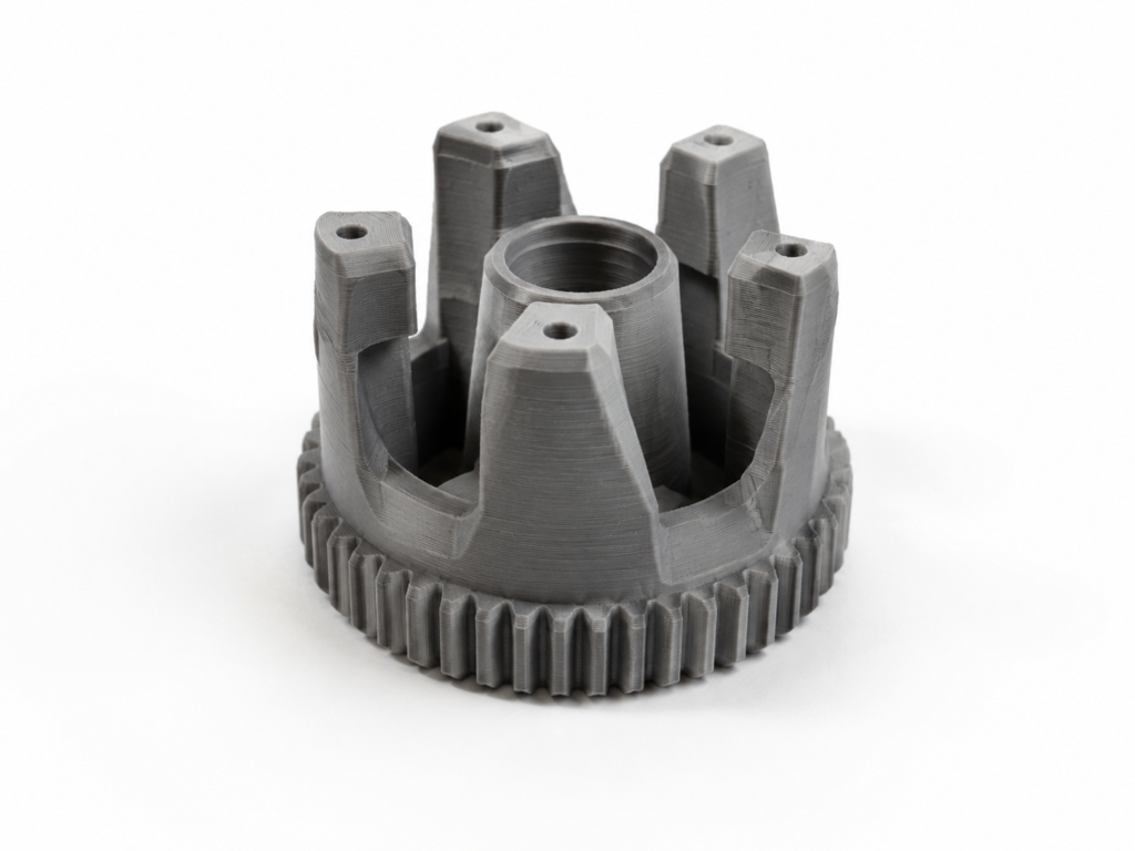
Prototyping with 3D Printing
3D printing is useful for early form, fit, and assembly checks before tooling. It supports fast design iteration, but printed material and surface behavior may differ from the final injection-molded part.
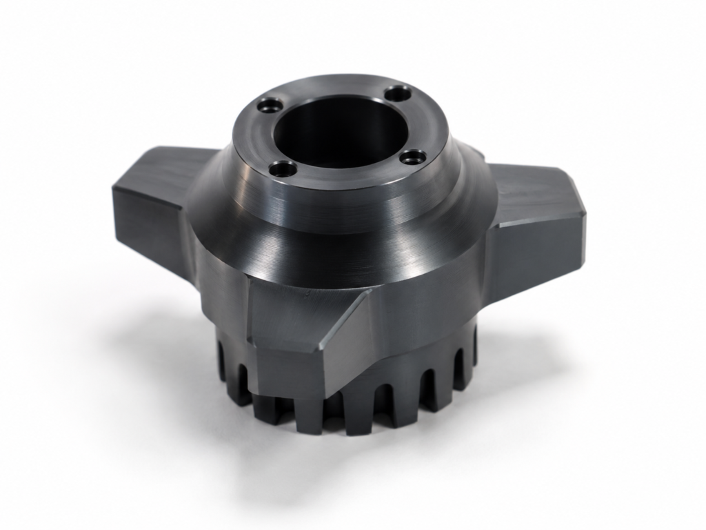
Prototyping with CNC Machining
CNC machining can produce functional prototypes from engineering plastics or metals with accurate features and production-like strength. It is useful when geometry, assembly, or load testing must be evaluated before mold investment.
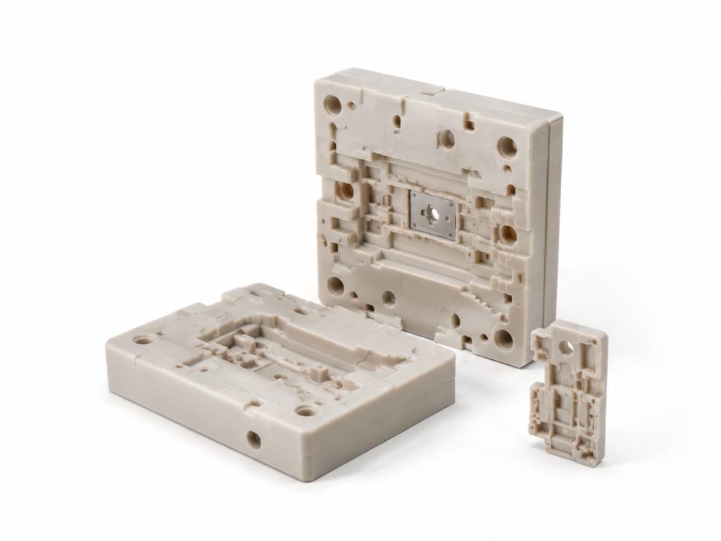
Prototyping with Low-Run Injection Molding
Low-run injection molding uses tooling and production resin to validate molded behavior, appearance, and assembly before larger-volume production. It requires more upfront preparation than 3D printing or CNC machining, so the choice should follow the project validation plan.
Low volume vs. medium vs. high volume injection molding
| Aspect | Low Volume (100–10,000) | Medium Volume (10k–100k) | High Volume (100k+) |
|---|---|---|---|
| Tooling Type | Aluminum / Soft Steel | P20 / H13 Steel | Multi-cavity Hardened Tooling |
| Lead Time | 1–5 Days | 1–2 Weeks | 2–4 Weeks |
| Cost per Part | $$ Medium | $ Low | $ Very Low |
| Investment | Low | Medium | High |
| Design Flexibility | ✔ Easy | ✖ Difficult | ✖ Very Difficult |
| Best For | Prototypes & pilot runs | Production ramp-up | Mass production |
Custom Surface Finish Options for Injection Molded Parts
Standard Finish
Moldmaker’s choice of finish. Typically SPI B-2, depending on geometry and drafts. Interior, non-cosmetic faces, are typically as-machined.
SPI Finishes
Range of Society of Plastics Industry (SPI) finishes from Grade 3 diamond / high polish to 320 stone low polish. Finishes include: SPI A-1, SPI A-2, SPI A-3, SPI B-1, SPI B-2, SPI B-3, SPI C-1, SPI C-2, SPI C-3, SPI D-1, SPI D-2, and SPI D-3Range of Society of Plastics Industry (SPI) finishes from Grade 3 diamond / high polish to 320 stone low polish. Finishes include: SPI A-1, SPI A-2, SPI A-3, SPI B-1, SPI B-2, SPI B-3, SPI C-1, SPI C-2, SPI C-3, SPI D-1, SPI D-2, and SPI D-3Range of Society of Plastics Industry (SPI) finishes from Grade 3 diamond / high polish to 320 stone low polish. Finishes include: SPI A-1, SPI A-2, SPI A-3, SPI B-1, SPI B-2, SPI B-3, SPI C-1, SPI C-2, SPI C-3, SPI D-1, SPI D-2, and SPI D-3
MoldTech Finishes (Mold Texturing)
Range of finishes including matte, swirls, lines, and patterns. Our most common texture finishes include: MoldTech MT11010, MoldTech MT11020, and MoldTech MT11030. Other textured finishes can be added by request.
Other Textures - VDI
VDI 3400 Surface Finish (commonly known as VDI surface finish) refers to the mold texture standard set by Verein Deutscher Ingenieure (VDI), the Society of German Engineers. This is mainly processed by EDM machining, producing fine to coarse matte finishes.
Threaded Inserts
We can install most commonly used standard inserts in UNF and metric sizes.
Pad Printing
Transfer a 2D image onto a 3D part. All images are subject to review.
Laser EngravingLaser Engraving
Engrave part numbers, logos, and more onto your parts.
Assembly
Elimold has the ability to assemble and label injection molded parts. Discuss your needs with your salesperson.Elimold has the ability to assemble and label injection molded parts. Discuss your needs with your salesperson.
CNC Machining Design Guide
Essential Design Tips for Engineers & Buyers to Ensure Quality Machined Parts
- Design for Manufacturability (DFM)
- Tolerance & Dimensional Control
- Surface Finish Selection
- Common Design Pitfalls to Avoid
- Material & Process Optimization
- Cost & Production Efficiency Consideration